
The supply voltage range vary between +5V and +15V.

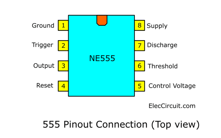
This is the positive supply voltage terminal of the IC. It toggles the output from high to low till voltage reaches 2/3 of the supply voltage When the voltage across the timing capacitor exceeds threshold value, the timing capacitor is discharged through this input. The amplitude of voltage applied to this terminal is responsible for the set state of the flip-flop in the IC. It compares the voltage applied to the terminal with a reference voltage of 2/3 of the Vcc. When the voltage at this input rises above the threshold value then the output will go from high to low. In both astable and monostable mode the voltage across the timing capacitor is observed through the threshold input. An external voltage applied to this pin can also be used to modulate the waveform output. Pin 5 determines the pulse width of the output waveform. When not in use it is recommended that this input should be connected to circuit ground using a 0.01uF capacitor. This enables you to vary the length of the output pulse in monostable mode or the output frequency in the astable mode. You can vary it from 45% to 90% of the main supply voltage. You can control the threshold voltage (pin 6) of the IC through the control input (which is internally set to 2/3 of the supply voltage). This input should remain connected to Vcc when IC is not in used. The voltage will be 1.7V lower than the main supply voltage.įor example, if the supply voltage is 5V output high voltage will be 3.3 volts and the output can source or sink up to 200 mA (maximum depends on supply voltage).Ī low voltage (less than 0.7V) is applied to the reset pin that will cause the output (pin 3) to go low. The output of the timer depends upon the amplitude of the external trigger pulse applied to this pin. This pin is responsible for transition of the flip-flop from set to reset. The output will remain high until a high voltage is applied to the threshold input (pin number 6). ground reference voltage.Ī low voltage (less than 1/3 the supply voltage) applied for a very short time to the trigger input that causes the output (pin 3) go high. This pin is connected to ground of the circuit i.e. The 555 timer IC is an integrated circuit (chip) which is used in a variety of timer, delay, pulse generation, and oscillator applications.įigure below shows the input and output signals of the 555 timer as they are arranged around a standard 8 pin dual inline package (DIP).


 0 kommentar(er)
